TOE 8800
Arbitrary Power Supplies from 160 W to 5200 W
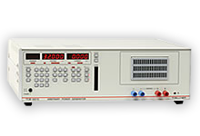
Arbitrary power supplies for generation of any voltage and current characteristics with an output power from 160 W to 5200 W. With exceptionally versatile and user-friendly software.
In addition to many predefined standard impulses for the automotive and avionics industries, the arbitrary power supplies of the TOE 8805 to TOE 88165 series additionally offer the option for generating completely optional waveforms. You can thus generate test voltages which perhaps may only be defined in the future.
They also provide dips and drops, load dump impulses, and many versions of complex voltages.
A comprehensive library of curves typical in vehicles provide the user with a reliable and versatile test instrument.
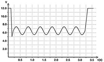
A further operating mode of these extremely universal arbitrary units is the simulation of wiring system ripple as encountered in vehicles or aircraft. Ripples with frequencies from 20 Hz up to more than 70 kHz can be superimposed on the test curves or on a pure DC voltage.
All models starting with the TOE 8825 are of modular design and consist of an intelligent control unit and boosters connected in parallel.
In these extremely universal units, the major features of a high-speed power supply have been optimally combined with those of an arbitrary function generator.
Software
The software included in the scope of delivery is extremely versatile, allows intuitive use, and permits generation of almost any waveforms within a very short time. Direct data importing from digital oscilloscopes and data recording equipment is also possible without problem.
Furthermore, the software has a library with standard curves from global vehicle manufacturers which is continuously updated.
Maximum output voltage
16 V to 100 V
Maximum output current
1.6 A to 320 A
Output power
160 W to 5200 W
Special features
- Generates any voltage and current characteristics
- Imports real-time signals from digital storage oscilloscopes or data recording systems
- Very high rise and fall rates of the output voltage: approx. 2 V/μs
- Brief load currents up to 1000 A
- User-friendly software
- GPIB and analog interfaces included as standard
- Vehicle electrics ripple: AC superimposition 4 Vpp
- 20 Hz to 70 kHz (TOE 8815 to TOE 8865)
- 20 Hz bis 50 kHz (TOE 8865 to TOE 88165)
- Internal sink function Brief load sink: 1000 W to 16000 W, depends on model
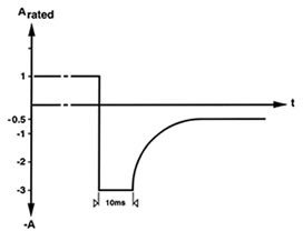
- Brief load current: 3 x Irated for approx. 10 ms (max. 1000 A)
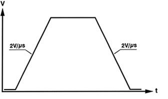 |
| Rise and fall times with TOE 8805 to TOE 88165 |
| XX=Voltage | 0 - 16 V | 0 - 18 V | 0 -20 V | 0 -24 V | 0 - 32 V | 0 - 40 V | 0 - 48 V | 0 - 64 V | 0 - 80 V | 0-100 V | Power |
| TOE 8805-xx | 0 - 10 A | 0 - 9 A | 0 - 8 A | 0 - 7 A | 0 - 5 A | 0 - 4 A | 0 - 3,5 A | 0 - 2,5 A | 0 - 2 A | 0 - 1,6 A | 160 W |
| TOE 8815-xx | 0 - 20 A | 0 - 18 A | 0 - 16 A | 0 - 14 A | 0 - 10 A | 0 - 8 A | 0 - 7 A | 0 - 5 A | 0 - 4 A | 0 - 3,2 A | 320 W |
| TOE 8825-xx | 0 - 40 A | 0 - 36 A | 0 - 32 A | 0 - 28 A | 0 - 20 A | 0 - 16 A | 0 - 14 A | 0 - 10 A | 0 - 8 A | 0 - 6,4 A | 640 W |
| TOE 8835-xx | 0 - 60 A | 0 - 54 A | 0 - 48 A | 0 - 42 A | 0 - 30 A | 0 - 24 A | 0 - 21 A | 0 - 15 A | 0 - 12 A | 0 - 10 A | 960 W |
| TOE 8845-xx | 0 - 80 A | 0 - 72 A | 0 - 64 A | 0 - 56 A | 0 - 40 A | 0 - 32 A | 0 - 28 A | 0 - 20 A | 0 - 16 A | 0 - 13 A | 1280 W |
| TOE 8855-xx | 0 -100 A | 0 - 90 A | 0 - 80 A | 0 - 70 A | 0 - 50 A | 0 - 40 A | 0 - 35 A | 0 - 25 A | 0 - 20 A | 0 - 16 A | 1600 W |
| TOE 8865-xx | 0 - 120 A | 0 -110 A | 0 -100 A | 0 - 80 A | 0 - 60 A | 0 - 50 A | 0 - 40 A | 0 - 30 A | 0 - 25 A | 0 - 20 A | 1920 W |
| TOE 8885-xx | 0 - 160 A | 0 -145 A | 0 -130 A | 0 -110 A | 0 - 80 A | 0 - 65 A | 0 - 55 A | 0 - 40 A | 0 - 32 A | 0 - 26 A | 2560 W |
| TOE 88105-xx | 0 - 200 A | 0 - 180 A | 0 -160 A | 0 -135 A | 0 -100 A | 0 - 80 A | 0 - 70 A | 0 - 50 A | 0 - 40 A | 0 - 32 A | 3200 W |
| TOE 88115-xx | 0 - 220 A | 0 - 200 A | 0 -180 A | 0 -150 A | 0 -110 A | 0 - 90 A | 0 - 77 A | 0 - 55 A | 0 - 45 A | 0 -36 A | 3600 W |
| TOE 88125-xx | 0 - 240 A | 0 - 215 A | 0 -195 A | 0 -160 A | 0 -120 A | 0 - 96 A | 0 - 80 A | 0 - 60 A | 0 - 48 A | 0 - 40 A | 3840 W |
| TOE 88145-xx | 0 - 280 A | 0 - 250 A | 0 -225 A | 0 -190 A | 0 -140 A | 0 -115 A | 0 - 95 A | 0 - 70 A | 0 - 56 A | 0 - 45 A | 4480 W |
| TOE 88165-xx | 0 - 320 A | 0 - 285 A | 0 -260 A | 0 -215 A | 0 -160 A | 0 -130 A | 0 -110 A | 0 - 80 A | 0 - 64 A | 0 - 52 A | 5200 W |
e. g.: 0 - 24 V, 0 - 56 A, 1280 W: TOE 8845-24
The arbitrary power supplies are equipped with an integral curve memory. They are thus able to execute entered curves autonomously, even without a PC connection. A burst function defines the number of desired curve sweeps.
Application examples
- Simulation of standard test pulses in accordance with ISO 7637-2, ISO 16750, DIN 40839
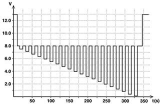
- Starting processes in vehicles (cranking)
- Simulation of real starting processes recorded in vehicles
- Troubleshooting with real recorded signals
- Line voltage ripple
- Dips and reset response
- Ramp-type rise and fall
- Determination and development of own specifications for developmentsklungen
- Defined charging processes for batteries
Curve is loaded via GPIB interface into the device-internal arbitrary memory.
 |
 |
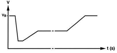 |
| ISO 7637-2, Pulse 4, start pulse |
Technical specifications
| Number of steps | 1000 |
| Step data | Voltage, current, step time |
| Step time | 200 μs to 100 s |
| Curve triggering | Manual, via GPIB or TTL signal |
| Number of sweeps | 1 to 255 or ∞ |
Software for curve generation
The new and extremely powerful software is used to generate freely-selectable waveforms. Both voltage and current waveforms can be generated.
Oscilloscope signals recorded in a vehicle can be read in directly and subsequently simulated. It is then possible to simulate, for example, voltage dips during the starting process and also noise voltages on the vehicle electrics rapidly and without problem.
Standardized test pulses from DIN 16750 or ISO 7637, such as load dump test pulses (also clipped), jump starts, reset response, and manufacture-specific test curves, can be simulated. These are included in the scope of delivery.
New and future versions of manufacturer- specific test curves can be generated rapidly and without problem.
Curve input
Curves can be generated within a short time using an easy-to-use GUI. No programming knowledge is required. Linear rise/fall as well as signal superimpositions such as sine, triangle, square and e-functions are possible. A table with numerical values is simultaneously generated parallel to the graphic input. Curve values can also be adapted and entered here in a convenient manner.
Data import
ASCII files can be read in using the import function. In this manner, oscilloscope signals from all well-known manufacturers can be imported without data adaptation.
It is thus also possible to import Excel tables which have been saved as CSV files. These real curves can be additionally varied using drag-and-drop. It is then possible e.g. to simulate the statuses of batteries.
Standard test pulses
A comprehensive library of waveforms with predefined standard curves from ISO 7637-2, ISO 16750 as well as manufacturer standards are included in the scope of delivery. These include the most important manufacturer pulses from Daimler, BMW, VW, Peugeot, Renault, etc. All components of these pulses can be changed as desired, without requiring an update liable to charges. You can therefore have new and future manufacturer versions available immediately without any waiting period. Your own modifications and adaptations are thus possible.
| Output Voltage | 0 - 16 V | 0 - 18 V | 0 - 20 V | 0 - 24 V | 0 - 32 V |
| Resolution Setting accuracy Measuring accuracy Monitor Voltage 0 to 10 V, accuracy |
1 mV 0.025 % + 10 mV 0.1 % + 10 mV 0.1 % + 10 mV |
1 mV 0.025 % + 10 mV 0.1 % + 10 mV 0.1 % + 20 mV |
2 mV 0.025 % + 10 mV 0.1 % + 10 mV 0.1 % + 20 mV |
2 mV 0.025 % + 10 mV 0.1 % + 10 mV 0.1 % + 20 mV |
2 mV 0.025 % + 10 mV 0.1 % + 10 mV 0.1 % + 20 mV |
| Voltage stabilization Change in load 0 to 100 % Change in line Voltage ± 10 % Change in temperature Residual ripple Vrms (bandwidth 1 MHz) Drift within 8 hours Regulation time with change in load from 20 % to 100 % and setting to within 0.2 % Vrated Setting time of output Voltage with change in setpoint, C = off (no-load/rated load) 0 V to Vrated. tr (10 to 90 %) typ. Vrated to 0 V. tf (90 to 10 %) typ. |
2 x 10⁻⁵ + 2 mV 5 x 10⁻⁵ 10-4/K 2.0 mVrms 10-4 < 600 μs < 10 μs < 10 μs |
2 x 10⁻⁵ + 2 mV 5 x 10⁻⁵ 10-4/K 2.0 mVrms 10-4 < 600 μs < 11 μs < 11 μs |
2 x 10⁻⁵ + 2 mV 5 x 10⁻⁵ 10-4/K 1.0 mVrms 10-4 < 300 μs < 12 μs < 12 μs |
2 x 10⁻⁵ + 2 mV 5 x 10⁻⁵ 10-4/K 1.0 mVrms 10-4 < 300 μs < 15 μs < 15 μs |
2 x 10⁻⁵ + 2 mV 5 x 10⁻⁵ 10-4/K 1.0 mVrms 10-4 < 300 μs < 20 μs < 20 μs |
| External Voltage control Control Voltage 0 to 10 V Accuracy Cut-off frequency (-3 dB). C = off. typ. |
0 - 16 V 0.1 % + 10 mV 3.5 kHz |
0 - 18 V 0.1 % + 20 mV 3.5 kHz |
0 - 20 V 0.1 % + 20 mV 3.5 kHz |
0 - 24 V 0.1 % + 20 mV 3.5 kHz |
0 - 32 V 0.1 % + 20 mV 3.5 kHz |
| Output Voltage | 0 - 40 V | 0 - 48 V | 0 - 64 V | 0 - 80 V | 0 - 100 V |
| Resolution Setting accuracy Measuring accuracy Monitor Voltage 0 to 10 V, accuracy |
5 mV 0.025 % + 10 mV 0.1 % + 10 mV 0.1 % + 30 mV |
5 mV 0.025 % + 20 mV 0.1 % + 20 mV 0.1 % + 30 mV |
5 mV 0.025 % + 20 mV 0.1 % + 20 mV 0.1 % + 30 mV |
5 mV 0.025 % + 20 mV 0.1 % + 20 mV 0.1 % + 30 mV |
10 mV 0.025 % + 20 mV 0.1 % + 20 mV 0.1 % + 40 mV |
| Voltage stabilization Change in load 0 to 100 % Change in line Voltage ± 10 % Change in temperature Residual ripple Vrms (bandwidth 1 MHz) Drift within 8 hours Regulation time with change in load from 20 % to 100 % and setting to within 0.2 % Vrated Setting time of output Voltage with change in setpoint, C = off (no-load/rated load) 0 V to Vrated. tr (10 to 90 %) typ. Vrated to 0 V. tf (90 to 10 %) typ. |
2 x 10⁻⁵ + 2 mV 5 x 10⁻⁵ 10-4/K 1.0 mVrms 10-4 < 200 μs < 25 μs < 25 μs |
2 x 10⁻⁵ + 2 mV 5 x 10⁻⁵ 10-4/K 1.0 mVrms 10-4 < 200 μs < 30 μs < 30 μs |
2 x 10⁻⁵ + 2 mV 5 x 10⁻⁵ 10-4/K 1.0 mVrms 10-4 < 200 μs < 40 μs < 40 μs |
2 x 10⁻⁵ + 2 mV 5 x 10⁻⁵ 10-4/K 1.0 mVrms 10-4 < 200 μs < 50 μs < 50 μs |
2 x 10⁻⁵ + 2 mV 5 x 10⁻⁵ 10-4/K 1.0 mVrms 10-4 < 200 μs < 60 μs < 60 μs |
| External Voltage control Control Voltage 0 to 10 V Accuracy Cut-off frequency (-3 dB). C = off. typ. |
0 - 40 V 0.1 % + 30 mV 3.5 kHz |
0 - 48 V 0.1 % + 30 mV 1.5 kHz |
0 - 640 V 0.1 % + 30 mV 1.5 kHz |
0 - 80 V 0.1 % + 30 mV 1.5 kHz |
0 - 100 V 0.1 % + 30 mV 1.5 kHz |
| Output current | Up to ≤ 5 A | Up to ≤ 10 A | Up to ≤ 20 A | Up to ≤ 40 A | Up to ≤ 80 A |
| Resolution Setting accuracy Measuring accuracy Monitor Voltage 0 to 10 V Monitor Voltage accuracy |
1 mA 0.1 % + 10 mA 0.1 % + 10 mA 0 - Irated 0.1 % + 10 mA |
1 mA 0.1 % + 10 mA 0.1 % + 10 mA 0 - Irated 0.1 % + 10 mA |
2 mA 0.1 % + 20 mA 0.1 % + 20 mA 0 - Irated 0.1 % + 20 mA |
2 mA 0.1 % + 40 mA 0.1 % + 40 mA 0 - Irated 0.1 % + 40 mA |
5 mA 0.1 % + 80 mA 0.1 % + 80 mA 0 - Irated 0.1 % + 80 mA |
| Current stabilization Change in load 0 to 100 % Change in line Voltage ± 10 % Change in temperature Residual ripple Irms (bandwidth 1 MHz) Drift within 8 hours Setting time of output current with change in setpoint, C = off (no-load/rated load) 0 A to Irated. tr (10 - 90 %) typ. Irated to 0 A. tf (90 - 10 %) typ. |
2 x 10⁻⁴ 10-4 2 x 10⁻⁴/K 0.5 mArms 5 x 10⁻⁴ < 0.2 ms < 0.2 ms |
2 x 10⁻⁴ 10-4 2 x 10⁻⁴/K 1 mArms 5 x 10⁻⁴ < 0.2 ms < 0.2 ms |
2 x 10⁻⁴ 10-4 2 x 10⁻⁴/K 1 mArms 5 x 10⁻⁴ < 0.2 ms < 0.2 ms |
2 x 10⁻⁴ 10-4 2 x 10⁻⁴/K 1 mArms 5 x 10⁻⁴ < 0.2 ms < 0.2 ms |
2 x 10⁻⁴ 10-4 2 x 10⁻⁴/K 1 mArms 5 x 10⁻⁴ < 0.2 ms < 0.2 ms |
| External current control Control Voltage 0 to 10 V Accuracy Cut-off frequency (-3 dB). C = off. typ. |
0 - Irated 0.4 % + 10 mA 3.5 kHz |
0 - Irated 0.4 % + 10 mA 3.5 kHz |
0 - Irated 0.4 % + 20 mA 3.5 kHz |
0 - Irated 0.4 % + 40 mA 3.5 kHz |
0 - Irated 0.4 % + 80 mV 3.5 kHz |
| Output current | Up to ≤ 120 A | Up to ≤ 160 A | Up to ≤ 200 A | Up to ≤ 260 A | Up to ≤ 320 A |
| Resolution Setting accuracy Measuring accuracy Monitor Voltage 0 to 10 V Monitor Voltage accuracy |
10 mA 0.1 % + 100 mA 0.1 % + 100 mA 0 - Irated 0.1 % + 100 mA |
10 mA 0.1 % + 100 mA 0.1 % + 100 mA 0 - Irated 0.1 % + 100 mA |
20 mA 0.1 % + 120 mA 0.1 % + 120 mA 0 - Irated 0.1 % + 120 mA |
20 mA 0.1 % + 130 mA 0.1 % + 130 mA 0 - Irated 0.1 % + 130 mA |
20 mA 0.1 % + 160 mA 0.1 % + 160 mA 0 - Irated 0.1 % + 160 mA |
| Current stabilization Change in load 0 to 100 % Change in line Voltage ± 10 % Change in temperature Residual ripple Irms (bandwidth 1 MHz) Drift within 8 hours Setting time of output current with change in setpoint, C = off (no-load/rated load) 0 A to Irated. tr (10 - 90 %) typ. Irated to 0 A. tf (90 - 10 %) typ. |
2 x 10⁻⁴ 10-4 2 x 10⁻⁴/K 1 mArms 5 x 10⁻⁴ < 0.2 ms < 0.2 ms |
2 x 10⁻⁴ 10-4 2 x 10⁻⁴/K 2 mArms 5 x 10⁻⁴ < 0.2 ms < 0.2 ms |
2 x 10⁻⁴ 10-4 2 x 10⁻⁴/K 2 mArms 5 x 10⁻⁴ < 0.2 ms < 0.2 ms |
2 x 10⁻⁴ 10-4 2 x 10⁻⁴/K 2 mArms 5 x 10⁻⁴ < 0.2 ms < 0.2 ms |
2 x 10⁻⁴ 10-4 2 x 10⁻⁴/K 2 mArms 5 x 10⁻⁴ < 0.2 ms < 0.2 ms |
| External current control Control Voltage 0 to 10 V Accuracy Cut-off frequency (-3 dB). C = off. typ. |
0 - Irated 0.4 % + 100 mA 2.0 kHz |
0 - Irated 0.4 % + 100 mA 2.0 kHz |
0 - Irated 0.4 % + 120 mA 2.0 kHz |
0 - Irated 0.4 % + 150 mA 2.0 kHz |
0 - Irated 0.4 % + 160 mV 2.0 kHz |
| Voltage/current | Separately on two 5-digit displays |
| Address | IEEE device address or memory address |
| Memory for instrument settings | 100 complete instrument settings for power supply mode and one setting in the non-volatile memory for the instrument status when switching off |
| Arbitrary function Interpolation points Interpolation point data |
2 to 1000 Voltage, current and step size |
| Step size | 200 μs to 100 s und ∞ separately adjustable for each interpolation point |
| Sequence mode | Continuous or burst with 1 to 255 sweeps |
| Triggering | Manually on keypad, remotecontrolled by bus command, or external trigger (TTL) |
| Saving | 1 complete function sequence with the data for 1000 interpolation points is saved in the internal non-volatile memory; external saving of function sequences on SRAM memory card according to JEIDA 4.0 standard with max. capacity of 2 MB |
| IEEE bus control Interface standard Software standard Device address Measuring rate |
Electrically isolated; in accordance with IEEE 488.1 In accordance with IEEE 488.2 0 to 30 > 8 measurements/s for voltage and current, > 12 measurements/s for voltage or current |
| Setting times | With a measurement taking place, extension of setting times by up to 100 ms |
| Voltage/current | < 50 ms |
| Capacitor | < 2 s (because of charging and discharging) |
| Power supply memory | < 150 ms for storage; < 50 ms « (< 2 s with capacitor switching) for recalling |
| Relay matrix | < 30 ms |
| Arbitrary function | < 30 ms for start < 30 ms for stop < 5 s for linear curve calculation, dependent on number of interpolation points < 200 ms for direct interpolation point storage < 50 ms for direct interpolation point recalling |
| Memory card | < 5 s for storage; < 5 s for recalling |
| Other | < 60 ms |
| Relay matrix Trigger Number of relays Contact rating |
Manually on keypad or remotecontrolled by IEEE bus command 4 relays with one NO contact each ≤10 W; ≤ 200 V und ≤ 0,5 A |
| Power output | Floating and electrically isolated, standby/execute directly switchable |
| Output terminals | TOE 8805, TOE 8815: at front, and parallel at rear TOE 8825, TOE 8835, TOE 8845, TOE 8855, TOE 8865, TOE 8885, TOE 88105, TOE 88125. TOE 88145, TOE 88165 at rear. |
| Insulation | ± 250 V against ground |
| Line voltage | 115 V/230 V ± 10 %, 47 Hz to 63 Hz |
| Power consumption | TOE 8805: approx. 360 VA TOE 8815: approx. 750 VA TOE 8825: approx. 1500 VA TOE 8835: approx. 2250 VA TOE 8845: approx. 3000 VA |
| Line voltage | 400 V ± 10 %, 47 Hz to 63 Hz, 3-phase |
| Power consumption | TOE 8855: approx. 3750 VA TOE 8865: approx. 4500 VA TOE 8885: approx. 6000 VA TOE 88105: approx. 7500 VA TOE 88115: approx. 8250 VA TOE 88125: approx. 9000 VA TOE 88145: approx. 10500 VA TOE 88165: approx. 12000 VA |
| Protective measures | Protection class 1 in accordance with DIN 57411/VDE 0411 Part 1 |
| Line fuse | 115 V: T 4 L 230 V: T 2,5 L for TOE 8805 115 V: T 8 L 230 V: T 4 L for each 320 W of output power in accordance with IEC 127-2/ III, DIN 41662 |
| Operating temperature | 0 °C to 40 °C |
| Reference temperature | 23 °C |
| Storage temperature | - 20 °C to 70 ° |
| Warm-up time | Approx. 30 min |
| Dimensions in mm | TOE 8805 216 x 132 x 437 mm (W x H x D), height with feet 147 TOE 8815 bis TOE 8865 434 x 134,5 x 437 mm (W x H x D), for each 320 W of output power |
| 19" Option | TOE 8805: 19“ system: systemcompatible with ½ 19“, 3 HU TOE 8815 - TOE 88165: system-compatible with 19“, 3 HU for each 320 W of output power |
| Housing | Aluminium |
| Weight | TOE 8805: approx. 9 kg TOE 8815 to TOE 88165: approx. 18 kg, or each 320 W of output power |
Options
Various options available for the TOE 8805 to 88165 arbitrary power supplies.
All options are used for specific adaptation of the arbitrary power supplies to the respective task. They can be fitted individually, and sometimes together.
TOE 8810/103
Brief load current 3 x Irated. Units equipped with this option deliver three times the rated current for approx. 10 ms.
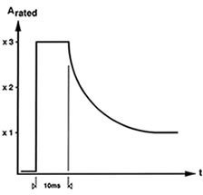 |
| Brief load current, optional TOE 8810/103 |
Vehicle electrics ripple / AC superimposition
The TOE 8810/107 option permits simulation of vehicle electrics ripple in the frequency range from 20 Hz to 70 kHz with an amplitude of 4 Vpp. Since this AC voltage is fed from an external signal generator, you can superimpose sine, triangle or square signals on the saved test curves or also on a pure DC voltage.
TOE 88107/107 M (only TOE 8815 to 88165)
Permits vehicle electrics ripple / AC superimposition in the frequency range from 20 Hz to 70 kHz and is simultaneously a brief load sink of 1 kW (for master device).
TOE 8810/107B
Like TOE 8810/107 M, but for booster devices. The brief load sink power per booster is approx. 1 kW.
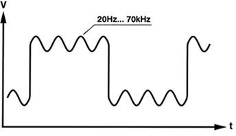 |
| Vehicle electric ripples with option TOE 8810/107 |
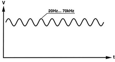 |
| Vehicle electric ripples with option TOE 8810/107 |
Sink mode
The TOE 8810/107 option is able in sink mode to rapidly discharge large capacitances. A sink current is briefly reached in the process which corresponds to three times the source current of the arbitrary power supply.
The TOE 8815-32 model, for example, provides a continuous output power of 320 W. A maximum brief load sink power of approx. 1000 W is achieved with the TOE 8810/107 option; a capacitance of 10000 μF can be discharged in this case from 14 V to 4 V in 3 ms.
 |
| Brief load sink with option TOE 8810/107 |
| Voltage version |
16 V |
18 V |
20 V |
24 V |
32 V |
40 V |
48 V |
64 V |
80 V |
100 V |
Output Power |
| TOE 8805 | - 16 | - 18 | - 20 | - 24 | - 32 | - 40 | - 48 | - 64 | - 80 | - 100 | 160 W |
| TOE 8815 | - 16 | - 18 | - 20 | - 24 | - 32 | - 40 | - 48 | - 64 | - 80 | - 100 | 320 W |
| TOE 8825 | - 16 | - 18 | - 20 | - 24 | - 32 | - 40 | - 48 | - 64 | - 80 | - 100 | 640 W |
| TOE 8835 | - 16 | - 18 | - 20 | - 24 | - 32 | - 40 | - 48 | - 64 | - 80 | - 100 | 960 W |
| TOE 8845 | - 16 | - 18 | - 20 | - 24 | - 32 | - 40 | - 48 | - 64 | - 80 | - 100 | 1280 W |
| TOE 8855 | - 16 | - 18 | - 20 | - 24 | - 32 | - 40 | - 48 | - 64 | - 80 | - 100 | 1600 W |
| TOE 8865 | - 16 | - 18 | - 20 | - 24 | - 32 | - 40 | - 48 | - 64 | - 80 | - 100 | 1920 W |
| TOE 8885 | - 16 | - 18 | - 20 | - 24 | - 32 | - 40 | - 48 | - 64 | - 80 | - 100 | 2560 W |
| TOE 88105 | - 16 | - 18 | - 20 | - 24 | - 32 | - 40 | - 48 | - 64 | - 80 | - 100 | 3200 W |
| TOE 88115 | - 16 | - 18 | - 20 | - 24 | - 32 | - 40 | - 48 | - 64 | - 80 | - 100 | 3600 W |
| TOE 88125 | - 16 | - 18 | - 20 | - 24 | - 32 | - 40 | - 48 | - 64 | - 80 | - 100 | 3840 W |
| TOE 88145 | - 16 | - 18 | - 20 | - 24 | - 32 | - 40 | - 48 | - 64 | - 80 | - 100 | 4480 W |
| TOE 88165 | - 16 | - 18 | - 20 | - 24 | - 32 | - 40 | - 48 | - 64 | - 80 | - 100 | 5200 W |
Ordering example
| TOE 8865-32 | 0 - 32 V, 0 - 60 A, 1920W |
Options
| TOE 810/103 | Brief load current 3 x Irated |
| TOE 8810/107M (only TOE 8815 to TOE 88165) |
External superimposition and brief load sink (master) |
| TOE 8810/107B | External superimposition and brief load sink (booster) |
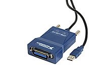
| TOE 9101 | USB GPIB controller |
| TOE 9009 | GPIB 488 cable, 2 m |
| TOE 9502 | 19" adapter, 3 HU for single installation, TOE 8805-xx |
| TOE 9508 | 19" adapter, 3 HU parallel installation set for 2 x TOE 8805-xx |
| TOE 9513 | 19" -Adapter, 3 HU for TOE 8815-xx to TOE 8825-xx |
 |
| TOE 9101 USB-GPIB-Controller |
Supplied accessories
- 1 power cord
- 1 instruction manual
- 1 memory card 128 KB
- Arbitrary software
- Software driver LabView